There are two kinds of digitizing: sketching where a boundary roughly goes, and drawing where it provably goes. The second kind, a wall exactly 12 meters long at exactly 45 degrees, a plot corner at surveyed coordinates, needs constraints, and in QGIS the constraints live in the Advanced Digitizing panel, a CAD-style dock that most users never open because a toolbar with a similar name distracts them. This guide separates the two surfaces, enables the panel, and teaches its working system: the distance, angle, and coordinate locks driven from the keyboard, parallel and perpendicular construction, construction mode, and continuous lock, as the QGIS documentation's editing chapter specifies them.
Home / GIS and Open Map Data for Beginners
QGIS Advanced Digitizing: The CAD Panel, Its Keyboard Locks, and Construction Mode

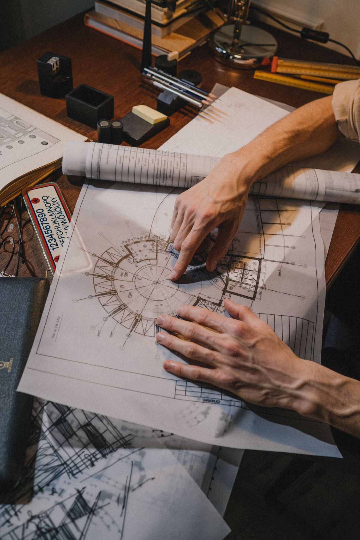
Photo: Ron Lach / Pexels
Interactive tool
Draw by Numbers: The CAD Panel Checklist
Check off each step as you finish it. Your progress stays on this page.
0 of 7 complete
0% done
Two Surfaces, One Name: Toolbar and Panel
First, the confusion to clear. The Advanced Digitizing toolbar is a row of editing tools: reshape features, split, merge, rotate, scale, fill ring, and their kin. It is useful and it is not this article's subject. The Advanced Digitizing panel is a dockable panel, enabled from the View menu under Panels (or by right-clicking a toolbar area and checking it), and once enabled it lights up whenever you are editing a layer and placing vertices. The panel is a constraint instrument: fields for distance, angle, X, and Y, indicators showing which constraints are active, and toggles for the construction helpers. If you have ever drawn a line in QGIS and wished the program would just let you type the length, the panel is that wish, implemented. Enable it once and it stays in your workspace, dormant outside edit sessions, awake the moment a vertex tool is.
The Keyboard Locks: d, a, x, and y
The panel's heart is four locks, each toggled from the keyboard while you draw:
| Key | Locks | Use it for |
|---|---|---|
| d | Distance from the previous vertex | Segments of exact length |
| a | Angle of the segment | Bearings, 45-degree walls, axis-aligned runs |
| x | The X coordinate of the next vertex | Vertical alignment at an exact easting |
| y | The Y coordinate of the next vertex | Horizontal alignment at an exact northing |
The workflow is tactile: start the line, move the mouse roughly toward the next corner, press d, type the length, Enter; press a, type the angle, Enter; click, and the vertex lands at the exact intersection of your constraints, not at wherever the mouse happened to be. Locked values show in the panel's fields, so the state is always visible, and pressing the key again releases that lock. Combine locks freely: distance plus angle is the surveyor's polar shot; X plus Y places a vertex at typed coordinates outright, the panel's answer to "put the corner exactly here." Angles are measured in the panel's terms (from the previous segment or absolute, per its settings), so check the mode once before a long session and the numbers will mean what you think they mean.
A Worked Example: A Rectangle of Exactly 12 by 8
Draw a building footprint with the panel and the system explains itself. Enable editing, choose the polygon tool, and click the first corner anywhere (or place it by X and Y locks if its coordinates are known). Press d, type 12, Enter; press a, type 0 (or 90, per the panel's angle convention in your setup), Enter; click: the second corner sits exactly 12 meters along the axis. Now d 8, angle turned 90 degrees from the last segment; click. Then d 12 back parallel to the first side; click. Close the polygon; the fourth side is forced by geometry to be 8 and parallel, and the panel's readouts have verified each segment as you drew it. Compare that with the freehand version, whose properties would read 11.87 by 8.23 at a jaunty angle, and the panel's purpose is fully argued. Buildings, plots, parking bays, sample quadrats, anything rectangular or dimensioned in the real world, digitize this way or not honestly at all.
Parallel and Perpendicular Construction
Real geometry is relational as often as it is numerical: this boundary runs parallel to that road; this wall meets that one at a right angle. The panel supports both directly. With the parallel or perpendicular mode armed (the panel's construction buttons, also reachable by keyboard while drawing), hover the reference segment and the panel constrains your next segment to run parallel or perpendicular to it, snapping the angle to the relationship rather than to a typed number. The angle field shows the derived value, so the relationship is verified, not assumed. These modes are how subdivisions, terraces, and building extensions get drawn consistently with what already exists, and they pair with the distance lock: perpendicular to the road and exactly 6 meters long is a driveway, specified the way a plan specifies it.
Construction Mode and Continuous Lock
Two toggles govern how constraints persist. Construction mode treats the vertices you place as scaffolding: the segments you draw with it guide the geometry (an offset line to measure from, a construction diagonal) without themselves becoming the feature's final shape in the way a normal segment does; it is the pencil line of CAD, drawn to be built upon. Continuous lock keeps a lock (distance is the classic case) applied to every subsequent segment until you release it, instead of expiring after one vertex: drawing a fence line of equal 5-meter panels, or a transect of equal steps, becomes click, click, click at guaranteed intervals. Together they move the panel from a measuring aid to a drafting system: scaffolding first, repeated exact steps along it, relationships enforced throughout. The snapping system, the subject of its own guide on this site, works underneath all of this, governing how vertices land on existing geometry; the panel governs the numbers, snapping governs the targets, and precision digitizing is the two in harness.
Reading the Panel While You Work
The panel is also an instrument readout, and learning to glance at it mid-draw is the skill that makes the locks trustworthy. It shows the current segment's live distance and angle as the mouse moves, the active locks, and the coordinates under the cursor, all updating continuously. Before each click, a half-second's check of the readout answers the only question that matters: is the vertex I am about to commit the vertex the numbers describe? Errors in constrained digitizing are almost never tool errors; they are a lock left on from three segments ago, or an angle mode misread once and faithfully repeated. The readout exists to catch both, and the habit of reading it is cheaper than the habit of redrawing. When a session ends, release the locks and close editing deliberately; constraints left armed greet the next feature like a trap set by a past self, because they are one.
Placing a Corner From a Survey: The X and Y Locks at Work
The polar workflow (distance and angle) builds geometry outward from itself. Surveyed work often arrives the other way: as coordinates computed elsewhere, corners whose eastings and northings are the deliverable of a total station or a GNSS occupation. The panel places those directly. Start the feature, press x, type the easting, Enter; press y, type the northing, Enter; click, and the vertex commits at exactly those coordinates, wherever the mouse is hovering. Repeat per corner and the polygon you draw is the survey, transcribed without a single mouse-dependent digit. The discipline this workflow demands is clerical rather than spatial: coordinates belong to a coordinate system, and the panel works in the layer's CRS, so a corner list in a different system must be transformed before it is typed, not after the shape looks wrong. Type the numbers into the right CRS, verify the first corner against a known reference on the canvas, and the rest can be trusted to the same arithmetic. This is the panel at its most literal: not helping you draw, but letting the numbers draw.
Panel Settings Worth Setting Once
Before a long precision session, spend one minute in the panel's own settings so its numbers speak your language. Set the angle measurement convention the job expects (the panel can report angles in the terms your plans and surveys use, and a session run in the wrong convention produces beautifully precise wrong lines). Confirm the units the distance field works in against the project's measurement settings, meters against feet being the classic silent disaster in shared projects. Decide whether locks should behave as one-shot or continuous for the task at hand rather than discovering the setting mid-fence-line. And glance at the panel's readout of the layer's snapping state, because the panel and the snapping system divide the work (numbers against targets) and a session with snapping unknowingly off produces exact segments ending near, not on, the geometry they were meant to meet. One minute of settings, verified once, is the cheapest insurance in the whole digitizing craft; the panel rewards the users who treat it as an instrument to be calibrated, not a toolbar to be poked.
The Panel and the Vertex Tools: A Division of Labor
It is worth stating plainly how the panel relates to the ordinary editing tools, because new users sometimes enable it and wait for it to draw something. The panel draws nothing. The vertex and feature tools (add feature, node tool, and their kin) remain the hands; the panel is the measuring instrument the hands consult, constraining each placement at the moment it happens. Work therefore alternates focus: eyes on the canvas to aim, eyes on the readout to verify, click to commit. Sessions go wrong in a recognizable way when that alternation collapses, when a user aims carefully and clicks without the verifying glance, trusting that the locks set three features ago are the locks this feature wants. They rarely are. The panel's whole design, its persistent fields, its visible lock states, its live numbers, is an argument that precision is a rhythm rather than a setting: aim, verify, commit, repeated until the geometry is done. Learn the rhythm and the individual locks become what they should be, unremarkable, like the pedals of a car an experienced driver no longer thinks about.
Related Guides
If this page answered part of the question, these GIS guides cover the rest of the same ground:
- QGIS Processing Toolbox: Run, Batch, Model, Repeat: What happens to precisely drawn layers next.
- QGIS Symbology: Single, Categorized, and Graduated Styles: Styling the features the panel helps you draw.
- QGIS Rename Field: Alias, In-Place Rename, and Refactor Fields: The schema side of the layers you are editing into.
- QGIS Attribute Table: Read, Sort, Filter, and Edit in Place: Verifying the features you placed, in the table.
Frequently Asked Questions
How do I enable the Advanced Digitizing panel in QGIS?
Enable it from the View menu, under Panels, choose Advanced Digitizing Panel (or right-click a toolbar area and check it in the panel list). It activates during editing sessions when a vertex tool is in use. Do not confuse it with the Advanced Digitizing toolbar, which is a separate row of reshape and split tools.
How do I draw a line of an exact length in QGIS?
With the Advanced Digitizing panel active and a line started, press d to lock distance, type the length, and press Enter. The next vertex is constrained to exactly that distance from the previous one. Add a with a typed angle to fix the direction as well.
What do the d, a, x, and y keys do while digitizing?
They toggle the panel's locks: d locks the distance from the previous vertex, a locks the segment's angle, x locks the next vertex's X coordinate, and y locks its Y coordinate. Pressing a key again releases its lock, and the panel's fields show which locks are active.
How do I draw parallel or perpendicular lines in QGIS?
Arm the parallel or perpendicular construction mode in the Advanced Digitizing panel while drawing, then hover the reference segment. The panel constrains your next segment to that relationship and shows the derived angle, and you can combine it with a distance lock for an exact offset feature.
What is continuous lock in the Advanced Digitizing panel?
Continuous lock keeps a constraint, most often distance, applied to every following segment until you release it, instead of expiring after one vertex. It is the fast way to draw repeated exact steps, such as equal fence panels or transect intervals.
Photo credits: Ron Lach (Pexels); Ron Lach (Pexels). Photos are served from this site; follow the credit to the library page for the original.